I’ve been hardware hacking recently, back using PIC microcontrollers. I have a few specific things I’d like to build – temperature sensor network, and metal lathe tachometer. But so far, I’ve just been getting back up to speed with all my bits & bobs. Hardware is brutually binary. It either works or it doesn’t. Typically, each circuit spends an evening in “doesn’t work” and then the next evening I immediately realise my mistake and it springs into “working” mode.
So far, I’ve built working circuits for:
- 555 timer clocking a manual switch into a 74HC164 shift register; net result: 8 LEDs go on and off.
- 16F84 PIC microcontroller with LEDs on the output pins: net result: 8 LEDs go on and off
- 16F84 PIC talking to DS1820 1-wire digital temperature sensor: net result, 8 LEDs go on and off, but tell you how warm it is
- USB cable from laptop to FTDI245BM breakout board (in bitbang mode): net result, 8 LEDs go on and off.
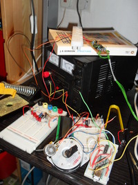
- FTDI245 connected to L293 H-Bridge controlling a bipolar stepper motor: net result, motor spins back and forth very precisely
- Finally, 16F84 PIC talking to a 16×2 LCD screen: net result, LCD says “hello world”
So, a reasonable wander around the world of digital electronics. Fortunately, I still had my “no part” PIC programmer from a few years back, although it took a while to find a PC which still has a parallel port, and took even longer to remember that it had to be set to SPP mode in the bios. Oh, and I don’t own a separate keyboard anymore, so changing BIOS settings was tricky.
Electronics is so unforgiving compared to software. Here’s a list of mistakes I’ve made – several times, usually:
- On my bench power supply, the ‘ground’ for the 0-30v range isn’t connected to the ‘ground’ for the 5v supply. That stopped the programmer working for a while, since it needs ~12.6v to program the PIC.
- You must compile/assemble PIC programs for precisely the right model of PIC that you have. There are many variants, and HEX files produced for one don’t always work for the other
- Ensure that the configuration word on the PIC is set up right. If you’re using a crystal oscillator, but the config word says you’re using an RC oscillator, it just won’t work.
- Ensure that the chip is the RIGHT WAY UP. Especially when you drop it on the floor. It appears that PICs are rather tolerant of this noobish mistake .. fortunately.
- Run your programs under gpsim first. Several times, I added an ‘include’ to the top of my main source file and accidentally ended up with the microcontroller executing the library functions as it’s main program. On a simulator, this is easy to see. IRL, it just dies silently.
- Be wary of CBLOCK sections in third-party code. By default, they assign addresses starting at 0 to symbols. But, the free registers on a 16F84 PIC start at 0xc, so you’ll end up trouncing system registers.
- In every circuit, have a status LED. Set up your code to blink it twice before it tries anything complicated, and use it as an “I’m alive” indicator throughout execution.
Anyhow, I now have an LCD screen working so I can get pretty output from my PIC rather than interpreting LEDs. Plus, I’m replacing my aging 16F84’s with newer 16F88’s. These have UARTs for serial comms, plus you can run a bootloader on them which simplifies programming greatly. In order to retire my parallel port, I’ve ordered an FTDI232 USB< ->serial breakout board.
My next project is to make a tachometer to measure the spindle speed on my lathe by using a metal disc with holes drilled round the edge. An LED shines through the hole onto a photo-transistor, and the PIC can measure the period of these pulses and hence the rotation speed. Then, with a few input buttons to allow me to set the material diameter, the PIC can also calculate the surface speed of the rotating material. This falls into the “kinda interesting, but not really necessary” category of projects. In other words, perfect hobby material.